ALL ABOUT CABLE DETECTION
Cable detection is a process of determining the existence of underground utilities by using specialized equipment to pick up signals that may naturally radiate from buried conductors.
We need the latest copy of topography survey in AutoCAD format, a detection drawing preferably with all site features captured and a decent site layout plan.
Detection instruments only picks up signals which is not a deciding factor to confirm if the cable is dead or alive. One can engage a Qualified Cable Jointer to do cable testing however the results may not be conclusive as well. As the status of any particular cable can be changed by its owner, it is best to seek the status of any cable from the owner directly.
Cables in general, except sewer, are laid 1 to 2m below ground level. They are laid deep enough to avoid any interference from the imposed weight of passing vehicles and also at a level catered for routine maintenance. As grounds may be topped up or trimmed off subject to earthworks carried out from time to time, it is not possible to tell the depth of the utilities by detection.
* Sewer lines are laid at a gradient with free gravity flow, it can be at 10m or deeper.
* Extra high voltage cables are usually laid deeper than the normal utilities. Beyond this depth are deep tunnel sewers and cable tunnels.
It depends. Some pipes can be picked up by a receiver alone while others may need signal injection to detect it. The level of detection is highly sensitive and it is dependent on site condition and its surrounding environment.
The detection drawing indicates the cable but not the number of cables for that area. It is possible that some other utilities which were not picked up by signals are also sitting within the vicinity of the same cable route.
There can be many factors affecting the results of site detection.
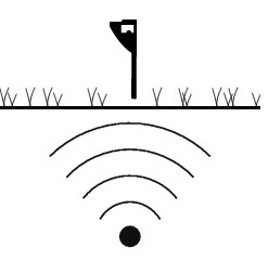
The primary factor is the signal strength of the target line. The signal must be strong enough for the instrument to pick up at ground surface. Its surrounding soil type, underground water table, salinity, the conductivity of the utility, etc play a decisive factor for a successful report.
Also, not all the utilities are detectable or can be easily detected. Eg. Ductile iron pipes are joint by spigot / socket with a rubber gasket. As the metal parts of such pipes are not in contact with each other, this makes detection very challenging as there is no conductivity of the whole pipeline.
In an underground environment there are different types of soil, underground water tables, salinity and the conductivity of the utilities, etc. Detection is carried out at vast land area often with overgrown and unknown complexity.
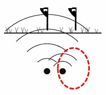
The job become tougher especially in areas where multiple signals of buried cables in close proximity are picked up irrespective of the one you are hoping to detect.
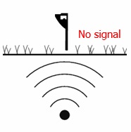
Scenario 1 – Utility is not detectable due to overcast signal
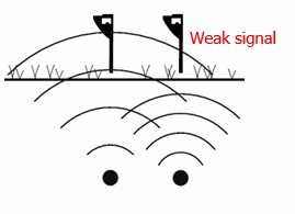
Scenario 2 – Utility is not detectable due to weak signal
No. Sub-Contractors should not use any Detection Reports that are not issued to them as there is no legal rights or protection if any unfortunate incident should happen.
A re-detection may be required for some of the following scenarios below:
- After the completion of cable diversion, and there’s a need to check further for live cables.
- There were new services laid in the areas detected.
- The existing road furniture in reference is removed, shifted and/or displaced.
- Detection markings were not visibly recognizable due to weather or other site activities.
ALL ABOUT PUBLIC UTILITIES
There are 25 utility providers, namely:
- SP PowerGrid
- SingTel
- StarHub Cable Vision
- StarHub
- SP Telecom
- BlueTel
- Flag Telecom
- Global Transit
- M1
- Matrix Network
- Netlink Trust
- Orange Carriers
- Reach Telecom
- Sparkle
- SuperInternet
- Superloop
- SuperSea
- Tata
- Telin
- Telstra Global (PacNet)
- Verizon
- ViewQuest
- PUB Water
- PowerGas
- PUB Sewer
The following information are required when requesting for service plans
- Lot Information of project site (Lot No.)
- Plan Type (Service Plan for drainage/sewerage/water)
- Requestor Details
It may take 1 to 4 weeks.
The main types of cables are:
- Low voltage cable in single phase – 230 volt
- Low voltage cable in 3 phases (red, yellow and blue phase) – 415 volt
- High voltage cable – 6P6kv (6,600 volt)
- High voltage cable – 22kv (22,000 volt)
- Extra high voltage cable (EHV) – 66kv (66,000 volt)
- Extra high voltage cable (EHV) – 230kv (230,000 volt)
- Extra high voltage cable (EHV) – 400kv (400,000 volt)
By their construction, there are oil filled / non-oil filled type; single core or multiple cores.
By their material, there are copper and aluminum.
By their insulation type, there are paper insulated and XLPE insulated cables.
The cables are generally black in color except 6p6kv is green and 22kv red. The latter may gradually fade/change and look a little black after some time.
No. E.g. most cables are of 75mm in diameter. High voltage cables in airfield is only 15mm in diameter.
Cable slabs are labels that are placed directly above the buried cables to provide visible markings for their underlying utilities. Used to come in red bricks in the early years, cable slabs are mostly concrete or in PVCs nowadays.
- Low voltage cables can be identified as:
Under red bricks with wordings like “SCC’, ‘SMC’, “PUB” or “public lighting”.
Under black PVC cable slabs with relevant wordings. - High voltage cables can be identified as:
Under concrete slabs with wordings like “EHT” and under yellow PVC slabs. - Extra High voltage cables can be identified as:
Under concrete slabs with wordings like “EHV”, “66KV”, “230KV”, “400KV”.
* Pilot Cables or small cables up to 25mm in diameter that function as control, monitoring or communication may be laid alongside HV or EHV cables.
Yes, besides using a direct buried method, cables can be laid within PVC pipes with draw pits/manholes at certain distant interval.
Power cables are of larger size (usually 150mm diameter) and communication cables in 100mm diameter. Smaller diameter tubes could be pulled into bigger pipes we call sub ducts which are mainly communication cables.
- For electricity: cable of 150mm / 100mm in diameter, usually sit under cable slabs for easy identification.
- For water: steel, cast iron, ductile iron, copper, stainless steel or PVC.
- For gas: steel, cast iron, ductile iron, copper, stainless steel or PVC.
- For gas: galvanized iron, cast iron, ductile iron, stainless steel or HDPE.
- For sewer: stoneware, PVC, cast iron, ductile iron or concrete.
A complex cable network is laid using multiple cables that may run beyond certain lengths or road contours to cater to different site conditions. Cable joints are the intersection points between two connecting cables.
The joints are the weakest part of the cable network and are most vulnerable to damage. You should take special attention for works at cable joints to avoid any earth movement that may potentially damage this part of the cable network.
TRIAL HOLE / TRENCH
The purpose of a trial hole is a pit for inspecting the existence and position of underlying utilities within that pit hole. We gather information like cable depth, size and quantity of these utilities exposed from these trial holes, prior to doing any excavation works.
Yes. Any form of earth removal or ground penetration including trial hole must have a valid NCE. The type of NCE required is dependent on the available utilities for that locality.
As soon as the NCE application is approved.
1. The indicated cable has not been exposed, it could be possibly laying in the pipe vicinity.
2. The pipes are carrying the power signal.